How to add DT support for a driver
The platform device scheme has been extensively used to describe hardware platforms. But its main disadvantage is the need to instantiate each device by code.
A modern way to describe the hardware is via device tree (DT).
There are kernel drivers that only support platform code, but the usage of device tree support on describing SoCs has been increasing. The idea of this post is to show a real example of how to add device tree support for a driver using the drivers/hwmon/sht15.c, as an example.
The code below shows how the file arch/arm/mach-pxa/stargate2.c uses the sht15 driver in platform data:
static struct sht15_platform_data platform_data_sht15 = {
	.gpio_data =  100,
	.gpio_sck  =  98,
};

static struct platform_device sht15 = {
	.name = "sht15",
	.id = -1,
	.dev = {
		.platform_data = &platform_data_sht15,
	},
};

static struct regulator_consumer_supply stargate2_sensor_3_con[] = {
	REGULATOR_SUPPLY("vcc", "sht15"),
};
DT support
The SHT11 sensor is present in the Click board SHT1x Click Module. This Click board can be plugged into the mikroBUS connector of the i.MX 7Dual SABRE-SD, a board that only support device tree. For a better understanding please open the link below containing the patch that enables the communication between the i.MX 7Dual SABRE-SD and the SHT1x Click Module: Patch SHT1x Click Module.
Documentation
All DT support needs a document to be accepted (and understood):
Documentation/devicetree/bindings/hwmon/sht15.txt
This document has to describe:
- Device name;
- Required properties (tip: if necessary, use “-“ to separate names);
- Optional properties, when necessary; and
- Example of the device tree source (dts file).
When a new device is added, if not present, its vendor needs to be included in the file below:
Documentation/devicetree/bindings/vendor-prefixes.txt
In this example, the vendor is Sensirion AG, and the patch below shows how to add it: Patch Vendor Sensirion
Driver modification
The driver can be found in:
drivers/hwmon/sht15.c
There are three modifications to implement in the driver:
1. Open firmware
For device tree support the Open Firmware header of.h is needed. As this driver works with gpio, this was included:
#include<of_gpio.h>
2. Probe function modifications
All drivers have a probe function, which works like a main function in a C program. This function gets all the hardware resources, such as memory, interrupts, GPIOS, etc.
In order to add device tree support into the driver the probe function needs to be changed, so that it can parse the device tree properties.
The “clean” way to do this is creating a secondary probe function to parse the DT properties.
Define the device tree user case (OF_CONFIG), the .compatible device and the device values MODULE_DEVICE_TABLE, including the secondary probe function to deal with this case:
#ifdef CONFIG_OF
static const struct of_device_id sht15_dt_match[] = {
	{ .compatible = "sensirion,sht15" },
	{ },
};
MODULE_DEVICE_TABLE(of, sht15_dt_match);

static struct sht15_platform_data *sht15_probe_dt(struct device *dev)
{
	struct device_node *np = dev->of_node;
	struct sht15_platform_data *pdata;

	/* no device tree device */
	if (!np)
		return NULL;

	pdata = devm_kzalloc(dev, sizeof(*pdata), GFP_KERNEL);
	if (!pdata)
		return ERR_PTR(-ENOMEM);

	pdata->gpio_data = of_get_named_gpio(np, "data-gpios", 0);
	if (pdata->gpio_data < 0) {
		if (pdata->gpio_data != -EPROBE_DEFER)
			dev_err(dev, "data-gpios not found\n");
		return ERR_PTR(pdata->gpio_data);
	}

	pdata->gpio_sck = of_get_named_gpio(np, "clk-gpios", 0);
	if (pdata->gpio_sck < 0) {
		if (pdata->gpio_sck != -EPROBE_DEFER)
			dev_err(dev, "clk-gpios not found\n");
		return ERR_PTR(pdata->gpio_sck);
	}

	return pdata;
}
#else
static inline struct sht15_platform_data *sht15_probe_dt(struct device *dev)
{
	return NULL;
}
#endif
Finally, change the original probe function to work with both cases. It is recommended to use the order platform data -> device tree in a logical way, to be able to handle errors too:
data->pdata = sht15_probe_dt(&pdev->dev);
	if (IS_ERR(data->pdata))
		return PTR_ERR(data->pdata);
	if (data->pdata == NULL) {
		data->pdata = dev_get_platdata(&pdev->dev);
		if (data->pdata == NULL) {
			dev_err(&pdev->dev, "no platform data supplied\n");
			return -EINVAL;
		}
 	}
3. Driver struct
In the last lines of the file, add the of_match_table into the struct platform_driver:
static struct platform_driver sht15_driver = {
	.driver = {
		.name = "sht15",
		.of_match_table = of_match_ptr(sht15_dt_match),
 	},
Device Tree Source
With the probe functions finished, remains to describe the properties parsed in the device tree case. The responsible for this is the dts file, and the example for this driver can be found in the link: Patch dts file.
The dts file is the device tree hardware description itself. Most of the time the needed pins are already in use and it is common to create a new dts file for each “external” device, as complement of the SoC.dts file.
This way, the dts file has at least two sections:
1. Driver Description
The driver description needs to inform exactly which device is being enabled and an overview about it:
sensor {
pinctrl-names = "default";
pinctrl-0 = <&pinctrl_sensor>;
compatible = "sensirion,sht15";
clk-gpios = <&gpio4 12 0>;
data-gpios = <&gpio4 13 0>;
vcc-supply = <®_sht15>;
};
This description needs to be the same used in the documentation example.
2. Driver pins
In the driver description there is a pincrtl value, which is used to configure the iomux function. When an iomux is set, the PAD been able to lead with 8 muxing options (called ALT modes). The communication between the Click Module and the i.MX 7Dual SABRE-SD depends of the correctly ALT mode configuration. The image below shows a demonstration of how to find the SHT1x Click Board SCL pin correspond communication in the i.MX 7Dual SABRE-SD schematic:
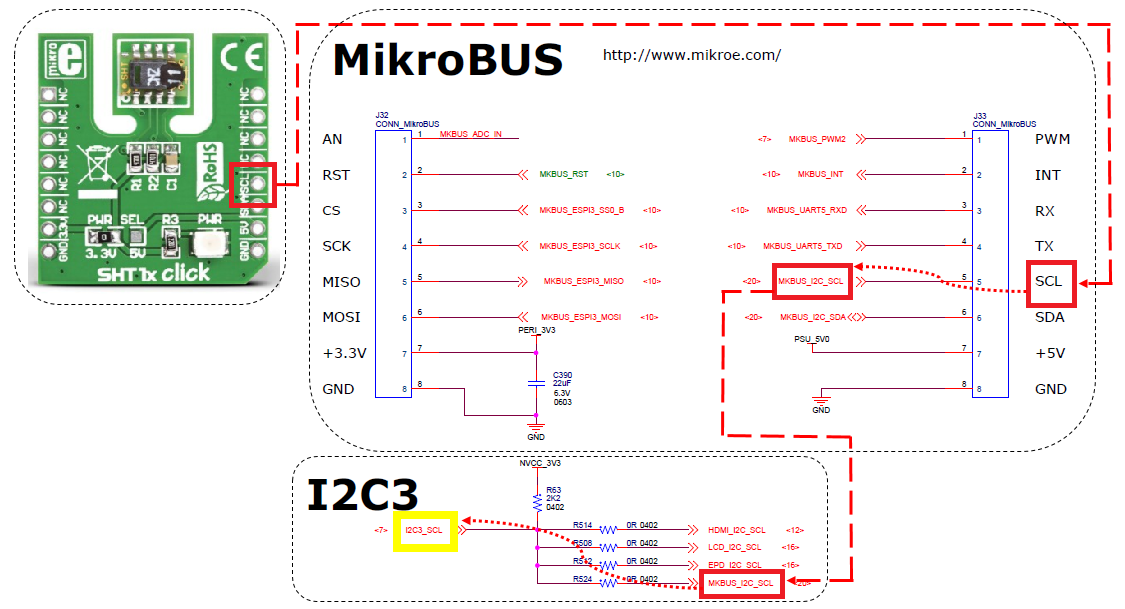
SHT11 does not work with I2C protocol, so in this case the CLK and DATA pins need to be configured as GPIO functionality. Search for I2C3_SCL in the i.MX 7Dual Reference Manual to find those GPIOs numbers:
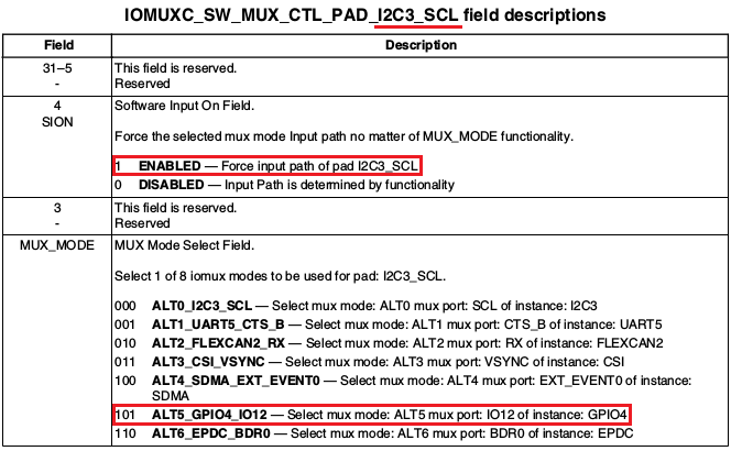
The image shows all the ALT modes possibilities, including how to use the i2c3 SCL as GPIO. This way, set as disabled the i2c3 and configure the iomux whit the GPIO number:
&i2c3 {
	status = "disabled";
};

&iomuxc {
	pinctrl_sensor: sensorgrp {
		fsl,pins = <
			MX7D_PAD_I2C3_SDA__GPIO4_IO13	0x4000007f
			MX7D_PAD_I2C3_SCL__GPIO4_IO12	0x4000007f
		>;
	};
};
Testing the new driver
After building the kernel, set up the new dts file:
=> setenv fdt_file 'imx7d-sdb-sht11.dtb'
=> saveenv
=> reset
Enter the command line below to get the local temperature:
cat /sys/bus/platform/device/sensor/temp1_input
Enter the command line below to get the local humidity:
cat /sys/bus/platform/device/sensor/humidity1_input