How to run and debug the Cortex-M4 on i.MX 7ULP using IAR Embedded Workbench
This post covers the required steps to setup the MCUXpresso BSP and IAR toolchain to run and debug the Cortex-M4 on the i.MX 7ULP SoC.
Hardware needed
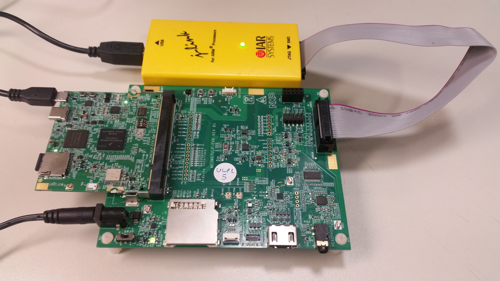
The picture above shows the hardware used in this tutorial. It contains the MCIMX7ULP-EVK board and J-Link JTAG probe. Equivalent JTAG probes should also work. The MCIMX7ULP-EVK board uses the low wire count SWD (Serial Wire Debug) configuration for accessing the Cortex-M4.
Toolchain
The IAR Embedded Workbench IDE needs to be installed in a Windows machine.
Note this software is not free and you need to pay attention on the limitations of the evaluation license.
Board Support Package
The BSP for Cortex-M4 is called “SDK” (Software Development Kit) and it can be downloaded at MCUXpresso website.
The steps to download the SDK and middleware source codes are explained on the section “Downloading the SDK” in this post:
The previous link explains how to build the image using GCC in a Linux machine, so this method is not covered here.
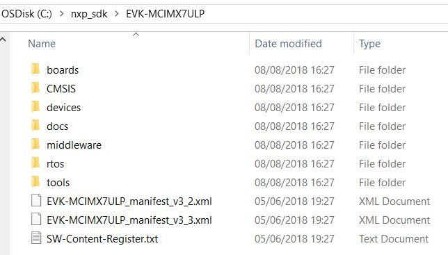
After downloading the SDK, extract the zip file. The folder structure is shown below:
Opening projects on IAR Embedded Workbench IDE
The application examples are stored in the folder below:
<sdk dir>\EVK-MCIMX7ULP\boards\evkmcimx7ulp\demo_apps
At the time of the writing of this post, the SDK version is 2.4.0 and there are 9 demo
examples on SDK. The example power_mode_switch and wireless_uart_bridge so far
are the only ones capable to boot properly the Cortex-A7 core (Linux). To know if the
application example provides the required PMIC (Power Management IC) commands to
fully initialize the Cortex-A7 core, refer to demo’s readme.txt file. The section
“Board Settings” inside the readme file details if the example is supported by the Linux BSP.
To open the project, double click the workspace file *.eww.
<sdk dir>\EVK-MCIMX7ULP\boards\evkmcimx7ulp\demo_apps\power_mode_switch\iar\power_mode_switch.eww
There are 2 ways for loading the code to the Cortex-M4, the first method is to load the code to the RAM (TCM RAM), the second is to program the external QuadSPI flash memory.
Loading the code to the RAM is faster for rapid debugging when several compile-debug interactions are needed, but it’s limited to 256kB for the code size, including stack.
To run the code from the RAM follow steps below:
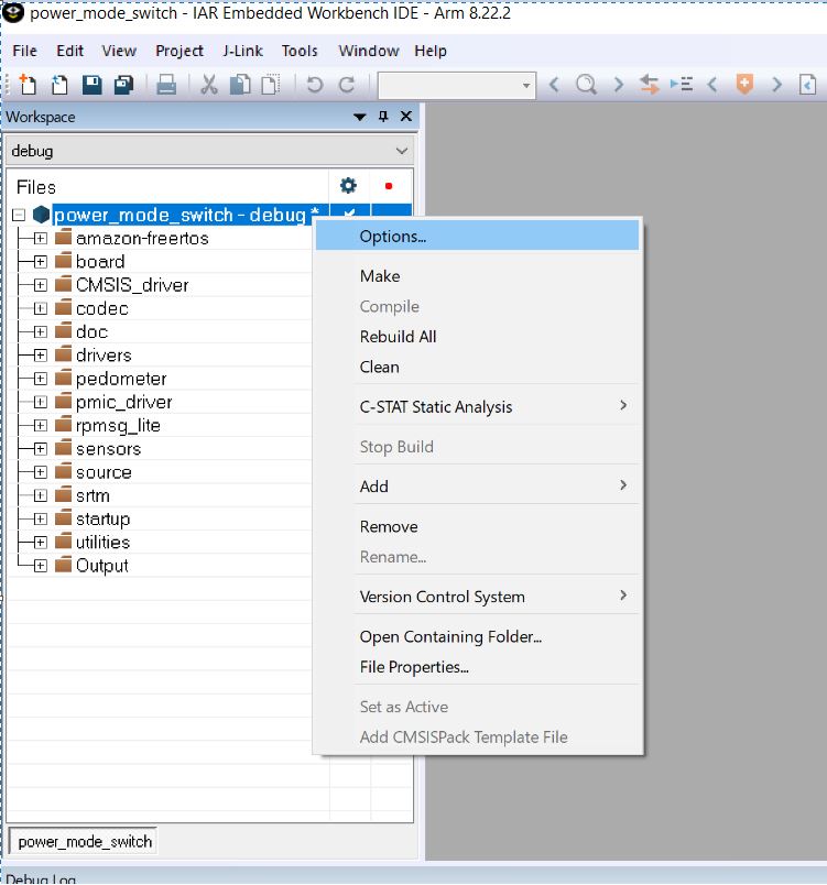
1: Right click on project name -> Options:
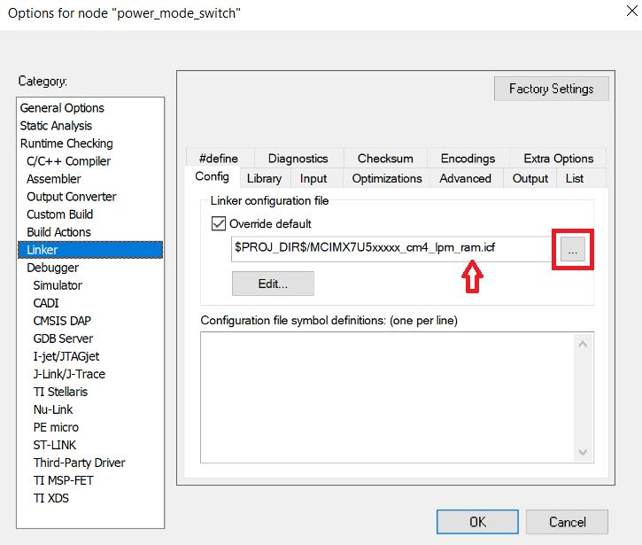
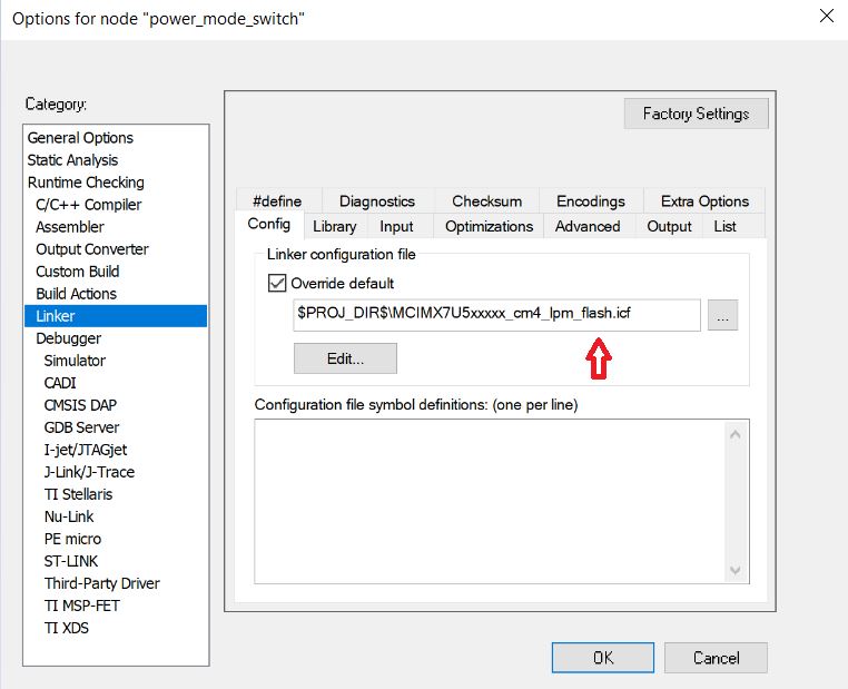
2: Click on Linker category, browse for the linker file to compile for the RAM memory:
3: Click on Debugger category and select the JTAG probe model attached to the board:
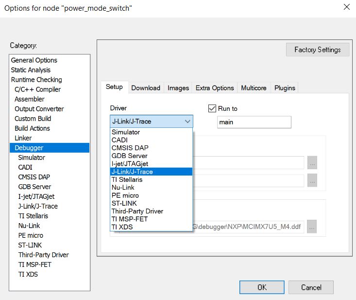
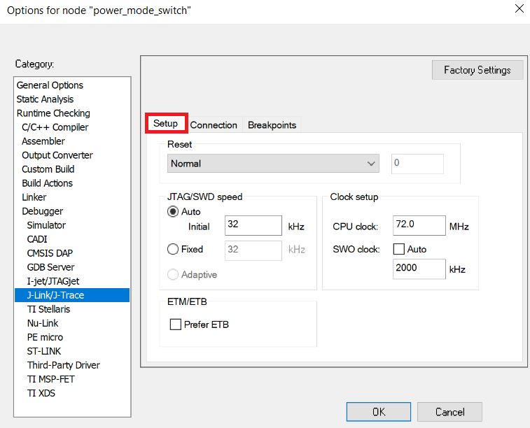
4: Click on the model of your debugger probe and at sub-category Setup, configure the parameters for the probe. For this particular example it’s being used the J-Link, so click on J-Link/J-trace:
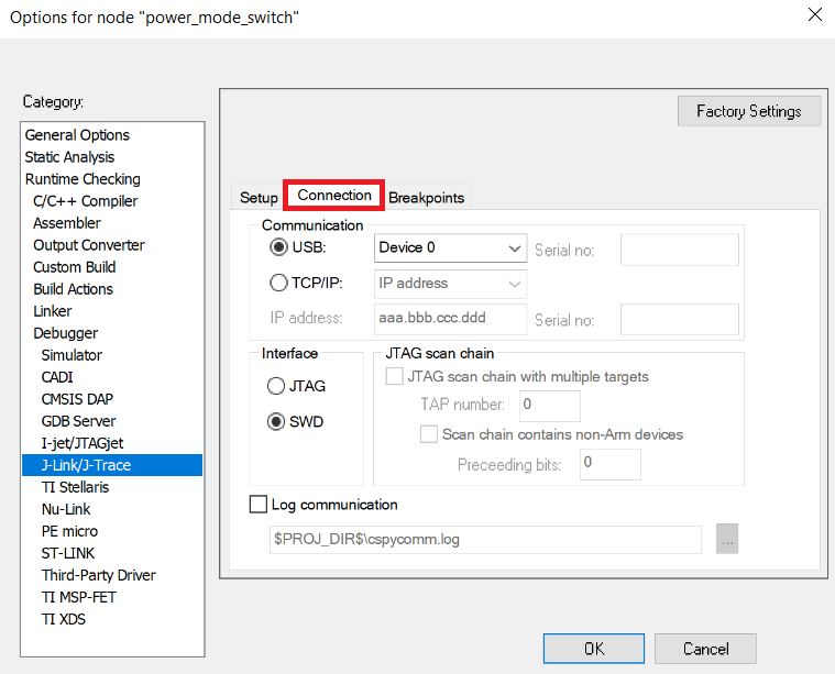
On Connection tab, make sure to select SWD instead of JTAG, as MCIMX7ULP-EVK uses SWD.
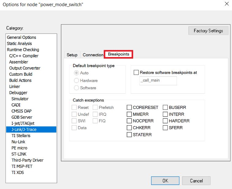
On Breakpoints tab leave as below:
Compiling and downloading the code to the RAM
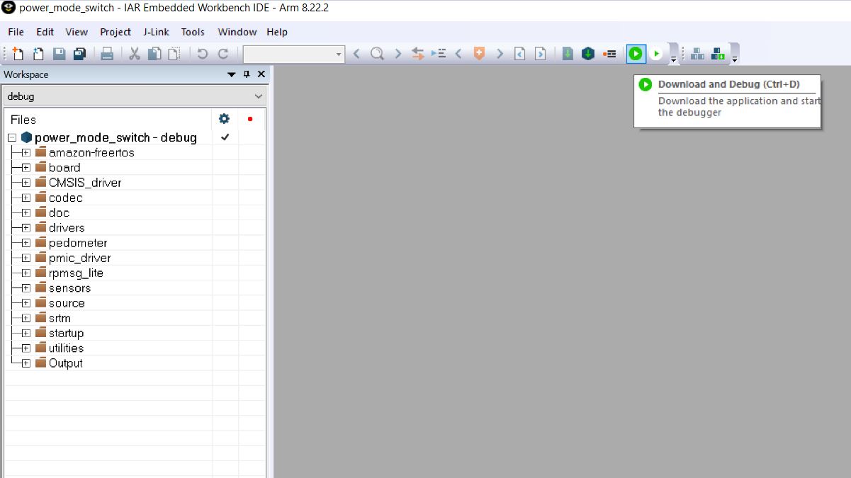
To compile and download the code, click on the green arrow Download and Debug (CTRL+D)
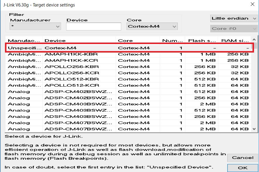
If the project doesn’t have the ARM core selected, just for the first time, select the Cortex-M4 as shown below:
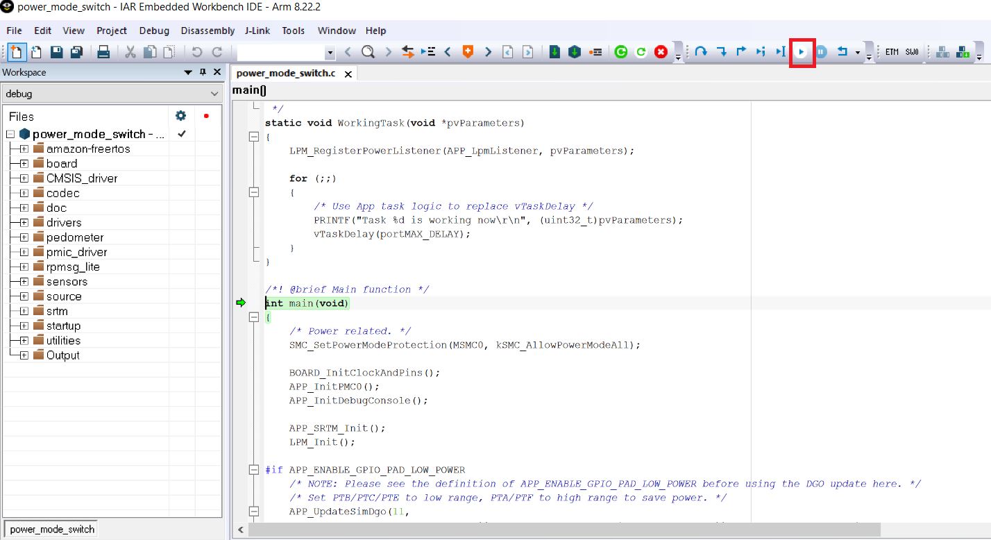
Code is then compiled, downloaded to the RAM and stops at the beginning of main()
routine. By pressing the arrow GO (F5), the code is executed.
The power_mode_switch example communicates though SCI @ 115200 8N1 (115200 baud rate;
8 data bits; No parity; One stop bit; No flow control). By pressing
“GO (F5)” the terminal receives data from Cortex-M4 SCI.
To add Breakpoints, right click on the line from C code you want to break at and
select Toggle Breakpoint (code)
If any power cycle occurs, the code is lost, as data in RAM is not retained.
Running the code from the QuadSPI external flash
Since the JTAG probe can’t communicate directly to the QuadSPI flash memory, the process to program this non volatile memory follows a different procedure. The binary needs to be copied to the MicroSD FAT Linux partition and then flash to QuadSPI memory using U-boot.
The instructions can also be viewed on the “Getting Started with MCUXpresso
SDK for i.MX 7ULP.pdf”. The file can be found inside the <sdk dir>\EVK-MCIMX7ULP\docs
folder. Refer to section: “6 Running an application from QSPI flash” for details.
In summary, the procedures are:
1: Similar as explained previously, go to Options -> Linker and select the flash linker file, as shown below:
2: Click on Make (F7). After the code compiles, the sdk20-app.bin file is
created in the folder:
<sdk dir>\EVK-MCIMX7ULP\boards\evkmcimx7ulp\demo_apps\power_mode_switch\iar\debug
This file needs to be converted to a specific format before downloading to QuadSPI
memory and this is done by the imgutil script that comes with the SDK package located at:
<sdk dir>\EVK-MCIMX7ULP\tools\imgutil
The imgutil script must be executed using Bash on a native Linux machine or
using Bash emulated in Windows.
Converting the binary to image file using a native Windows machine
In case you want to do all the procedures in a native Windows 10 machine, the Linux bash must be installed in Windows. There are several options to run Linux over Windows. This example covers the Ubuntu Bash in Windows 10. To install Ubuntu Bash on Windows 10 follow this procedure.
In case you want to run this procedure in a Linux machine, refer to append of this post.
To convert the sdk20-app.bin to sdk20-app.img follow these steps:
1: Copy the binary file sdk20-app.bin generated by IAR to the folder
<sdk dir>\EVK-MCIMX7ULP\tools\imgutil\evkmcimx7ulp
2: Using the Ubuntu Bash, navigate to the board folder:
$ cd /mnt/c/<sdk dir>/EVK-MCIMX7ULP/tools/imgutil/evkmcimx7ulp
3: Execute the mkimg.sh script:
$ ./mkimg.sh flash
4: Copy the sdk20-app.img file to the MicroSD card containing the Embedded Linux image.
The file needs to be copied to the FAT partition Boot root folder (where zImage
resides).
5: Remove the MicroSD from the computer.
Flashing the QuadSPI Memory
Insert the MicroSD into the MCIMX7ULP-EVK board and connect the USB cable to the
Debug USB connector. 2 virtual COM ports should be mounted. One for the Cortex-A7
and other for the Cortex-M4. Both COM ports must be configured @115200 8N1 baud.
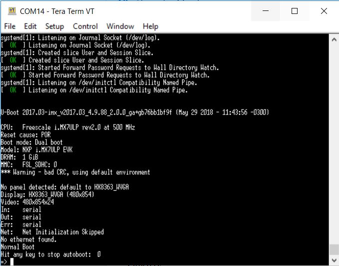
On the COM prompt for Cortex-A7 (Linux) press any key within 3 seconds after
power up to stop auto boot and enable the U-boot prompt. In this step you should
have this screen:
Execute below 4 commands to download the *.img file from MicroSD card
to the QuadSPI memory:
=> sf probe
=> sf erase 0x0 0x20000
=> fatload mmc 0:1 0x62000000 sdk20-app.img
=> sf write 0x62000000 0x0 0x20000
Done, you have completed the QuadSPI programming.
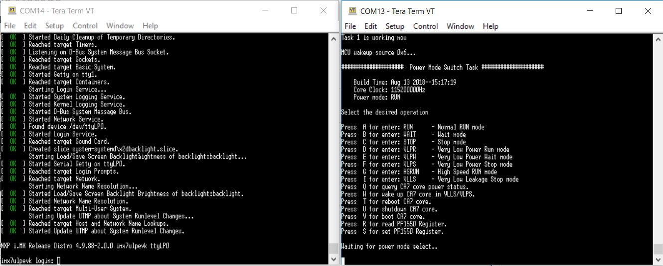
Now you can power cycle the board and the 2 cores send data to its respective
COM port. The M4 loads the application Power Mode Switch Task, and Cortex-A7
loads the Linux, like below:
If the Cores can’t communicate to console, remember to disconnect the JTAG flat
cable, or press RUN on the IAR IDE.
Running and Debugging the code from QuadSPI
Attach the J-Link probe to the board, power on and press the IAR button
Debug without Downloading. The code from QuadSPI is executed and stops
at main() routine. Note that if the “standard” Download and Debug (Ctrl+D)
button is pressed instead, it will also work, but warnings will be shown informing
the flash could not be programmed. This is caused by the IAR flashloader not being
able to program the QuadSPI memory.
If a new software version needs to be loaded to the Cortex-M4 QuadSPI memory, all the procedures to compile, convert the binary file and flash using U-boot must be executed again.
Append: Converting the binary to image file using a native Linux machine
To convert the sdk20-app.bin to sdk20-app.img using a Linux machine, follow
these steps:
1: In Windows, copy the folder imgutil <sdk dir>\EVK-MCIMX7ULP\tools\imgutil
to a memory stick:
2: Copy the binary file sdk20-app.bin generated by IAR to the folder “evkmcimx7ulp”
to the memory stick. Remove the memory stick from Windows.
3: Attach the memory stick to a Linux Machine
4: Copy the folder imgutil to your Linux PC.
4.1: Navigate to the evkmcimx7ulp folder and execute the mkimg.sh script:
$ ./mkimg.sh flash
By executing this script, the file sdk20-app.img is generated.
In case issues occur, verify the files permissions, If needed, give full permissions
to all imgutil folder by executing $ chmod 777 -R imgutil.
5: Copy the sdk20-app.img file to the MicroSD card containing the Embedded Linux image.
The file needs to be copied to the FAT partition Boot root folder (where zImage
resides).
6: Remove the MicroSD from the computer. Go to section Flashing the QuadSPI Memory.