MikroE RELAY Click board enablement on WaRP7
The WaRP7 IO board includes a mikroBUS connector which allows a large amount of Click boards to interact with the i.MX7S chip. This post discusses the enablement and use of the RELAY Click board with WaRP7.
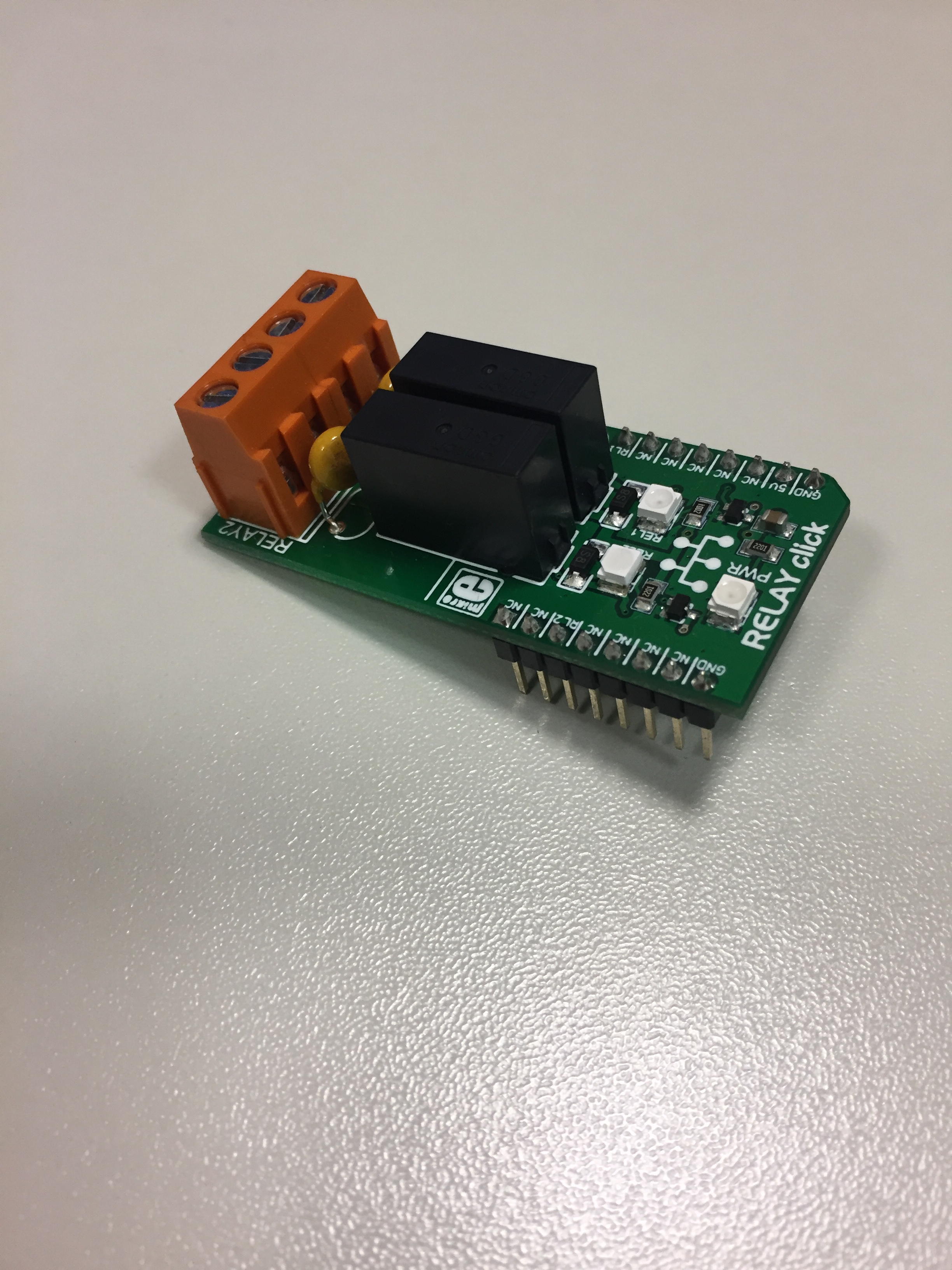
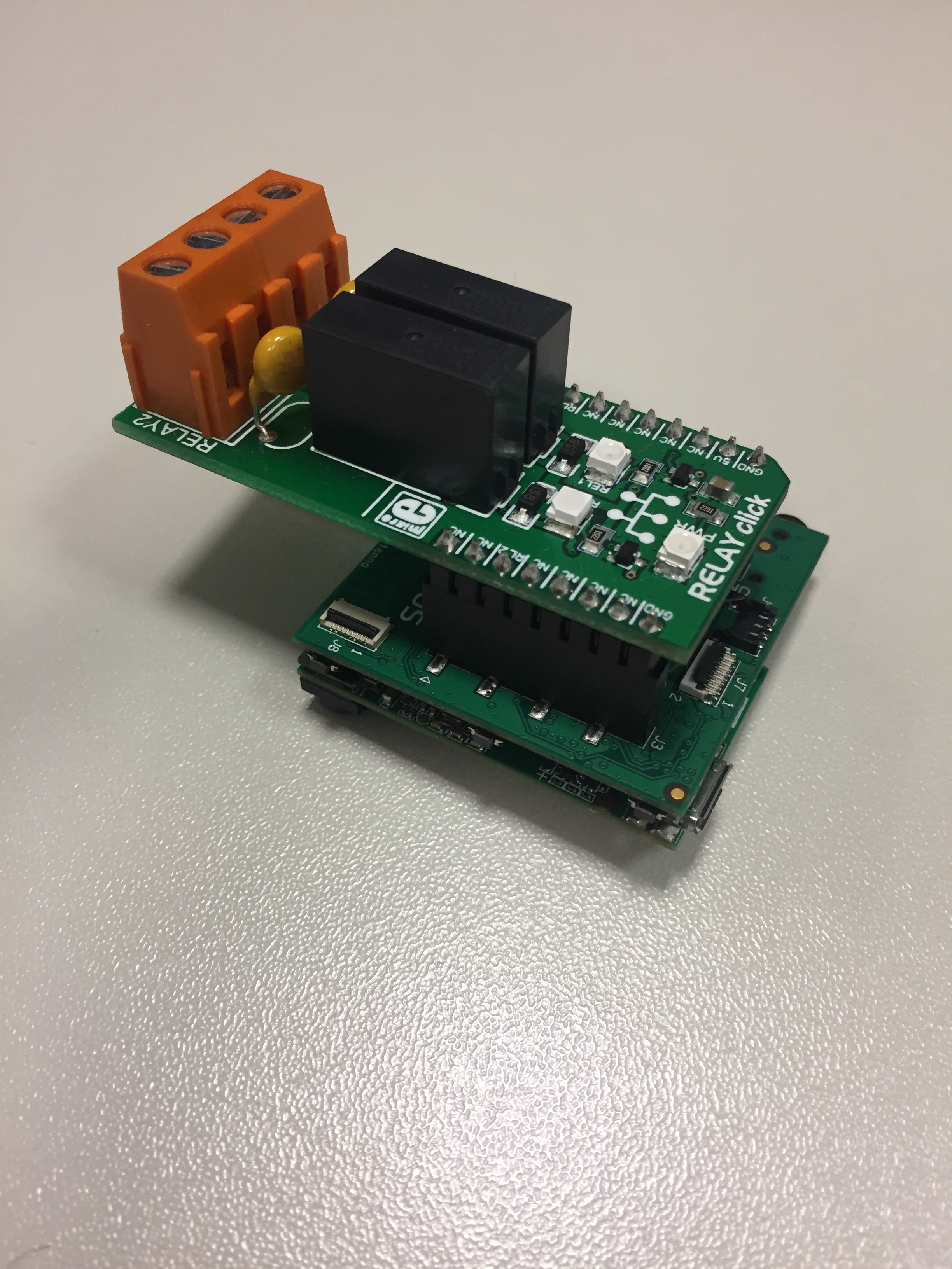
The RELAY Click board features two G6D1AASI-5DC power PCB relay modules as well as two screw terminals. It communicates with the WaRP7 via mikroBUS PWM (RL1) and CS (RL2) pins. A LED diode (Green) indicates the presence of a power supply. It controls up to 5A, 250V AC/30V DC loads. The board is designed to use 5V power supply only, but communication lines voltage level can be in a range between 1.8V and 5V. On-board transistors are used to drive relays by current sinking. In order to use the board connect it to the bottom of the WaRP7 IO board in the following way:
Once the board is connected, boot your WaRP7 board. After reaching the Linux prompt, the first step is to enable the GPIOs. GPIO 200 is connected to PWM (RL1) and GPIO 119 to CS (RL2). Use the following commands for enablement:
$ cd /sys/class/gpio
$ echo 200 > export
$ echo 119 > export
These commands enable GPIOs 200 and 119 to be use with the RELAY board connectors. After this step you can manipulate each relay following the instructions below:
For relay RL1
$ cd gpio200
$ echo out > direction
$ echo 1 > value
$ echo 0 > value
For relay RL2
$ cd gpio119
$ echo out > direction
$ echo 1 > value
$ echo 0 > value