Setting boot configuration on i.MX
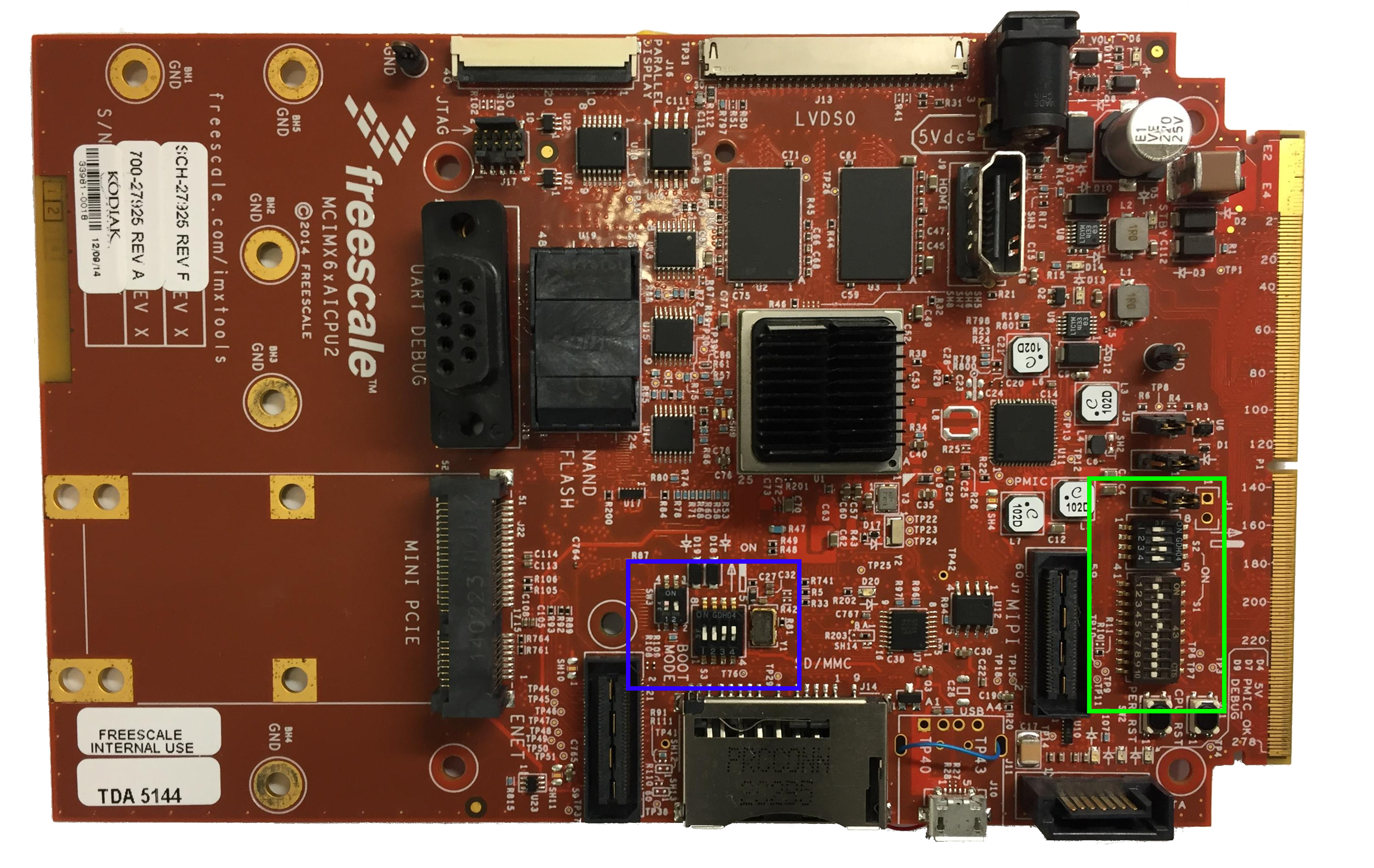
The i.MX development boards include boot switches that can be configured as desired. This configuration is used by the Boot ROM program on a Power On Reset (POR) to define the boot setup, for example at this point is defined which boot storage device the system has to use.
In this post we are going to use as an example the i.MX6Q SabreAuto board, but the same concept can be applied in most of the i.MX development boards.

Some of the procedures in this post includes burning eFuses, if you don’t know how to do it and its consequences please check the post Burning eFuses on i.MX6 and i.MX7
Boot modes
The boot mode is defined by the SW3-2 and SW3-3 as in the table below, for a more detailed information about the boot modes please check the “Boot modes” section in the processors reference manual.
| Boot Mode | Fuses | Serial Downloader | Internal Development | Reserved |
|---|---|---|---|---|
| SW3-2 | 0 | 1 | 0 | 1 |
| SW3-3 | 0 | 0 | 1 | 1 |
The pins BOOT_MODE0 (SW3-2) and BOOT_MODE1 (SW3-3) are the first bits to be
read by the ROM for defining the device behavior.
-
Fuses: This mode is similar to the Internal Development mode, but the GPIO pins are ignored and only the eFuses are used for defining the boot setup. This mode can be also achieved by burning the eFuse
BT_FUSE_SEL 0x460[4]. -
Serial Downloader: In this mode it’s possible to download an image to the memory through the USB port. When this mode is enabled the boot flow goes directly to the Serial Downloader mode.
-
Internal Development: In this mode the ROM boot runs into the default flow, if the eFuse
BT_FUSE_SEL 0x460[4]is not set the ROM will use the General Purpose I/O (GPIO) pins for determining the booting setup. Usually this mode is just used for development purpose, in deployed products it’s recommended to boot from eFuses.
Booting from GPIO
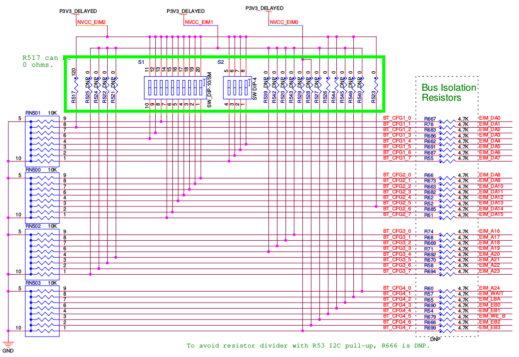
Usually the i.MX development boards are already configured by default for booting from GPIO in internal mode, some of the configuration GPIOs can be easily toggled by setting the switches SW-1 and SW-2. The remaining GPIOs can be modified by populating or depopulating resistors. The resistors and switches can be located in the boards schematics.

For example the following table shows different setups for booting the board using various storage devices, the default setup is booting from the SD Card on the CPU board.
| Boot Config Switch | Nand Flash 64 GB | Nand Flash 16GB | Parallel NOR Flash | SD on CPU Card | MMC on CPU Card | Sata HDD | Serial NOR Flash |
|---|---|---|---|---|---|---|---|
| SW2-1 | * | * | 0 | * | * | 0 | 1 |
| SW2-2 | 0 | 0 | 0 | 0 | 1 | 1 | 1 |
| SW2-3 | X | X | 0 | 1 | 1 | 0 | 0 |
| SW2-4 | 1 | 1 | 0 | 0 | 0 | 0 | 0 |
| SW1-1 | 0 | 0 | X | * | * | * | X |
| SW1-2 | 0 | 0 | X | 1 | * | * | X |
| SW1-3 | 0 | 0 | X | X | * | * | X |
| SW1-4 | 1 | 1 | X | 0 | 0 | * | X |
| SW1-5 | 0 | 0 | X | 1 | 1 | * | X |
| SW1-6 | X | X | 1 | * | * | X | X |
| SW1-7 | X | X | 0 | * | * | X | X |
| SW1-8 | 0 | 0 | X | * | X | X | X |
| SW1-9 | 0 | 0 | X | * | X | X | X |
| SW1-10 | 0 | 0 | 0 | * | * | X | X |
Depending on the application additional configurations have to be set, for a complete list of each boot configuration bit please refer to the section “Boot Devices (Internal Boot)” on the processors reference manual.
Booting from eFuses
By default the boot configuration eFuses are not burnt, for booting from eFuses
it’s necessary to burn the BT_FUSE_SEL 0x460[4] fuse or set the boot mode
switch to BOOT_MODE[1:0].
For example, for booting from the SD Card on the CPU board the following eFuses have to be burnt:
- BT_FUSE_SEL
- BT_CFG1_6
- BT_CFG2_1
- BT_CFG2_4
Procedure in U-Boot:
- Burn 0x460[4] - BT_FUSE_SEL
=> fuse prog 0 6 0x00000010
- Burn 0x450[6] - BT_CFG1_6
=> fuse prog 0 5 0x00000040
- Burn 0x450[9] - BT_CFG2_1
=> fuse prog 0 5 0x00000200
- Burn 0x450[12] - BT_CFG2_4
=> fuse prog 0 5 0x00001000
Procedure in user space (if available):
# cd /sys/fsl_otp/
- Burn 0x460[4] - BT_FUSE_SEL
# echo "0x00000010" > HW_OCOTP_CFG5
- Burn 0x450[6] - BT_CFG1_6
# echo "0x00000040" > HW_OCOTP_CFG4
- Burn 0x450[9] - BT_CFG2_1
# echo "0x00000200" > HW_OCOTP_CFG4
- Burn 0x450[12] - BT_CFG2_4
# echo "0x00001000" > HW_OCOTP_CFG4
For a complete list of boot configuration eFuses please check the fusemap chapter on the processors reference manual.